

Key Takeaways
- Face milling is a fundamental machining process for producing precise flat surfaces, where cutter geometry, spindle speed, and proper tool selection significantly influence both material removal rates and surface finish quality.
- To get the best results, you’ll need to prepare your workpiece, set up your machine and choose cutting parameters, like spindle speed, feed rate and depth of cut, for your material and project.
- Choosing the appropriate face milling tool — whether indexable face mills, shell mills, or fly cutters — can be the key to unlocking efficiency, minimizing tool wear, and achieving the perfect finish across applications.
- Regular process monitoring (checking tooling condition, coolant strategies, and making parameter adjustments) ensures continued performance, tool life, and finish.
- By grasping what sets face milling apart from peripheral, end, and slot milling, machinists can identify the optimal approach for every machining operation, enhancing efficiency and component precision.
- Knowing about surface finish, as well as how to avoid tool wear and how to use modern finishing tools, is key for machining components that are both functional and beautiful in today’s cutthroat manufacturing world.
Face milling is a machining operation in which a rotating cutter removes material at the workpiece surface to leave a flat finish. The tool is multi-toothed so it’s fast and good for big flat parts in steel and softer metals. Plates are common in many shops, using face milling to maintain tight tolerances and high speeds in automotive, aerospace and metal work.
Cutter choice, feed rate and cutting speed all affect the surface finish and tool life, so shops adjust these for every job. Face milling is compatible with both manual and CNC machines — making it a popular choice for a variety of work.
The following sections discuss more about cutter types, setup and best practices for strong results.
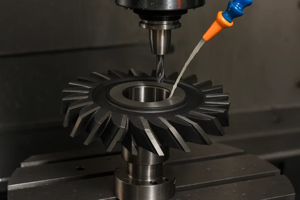
What Is Face Milling?
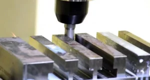
Face milling is a technique that contours flat surfaces. It utilizes a rotating multi-toothed cutting tool. The cutter spins at a high speed and takes shallow passes, shaving off layers of the surface.
It’s a popular choice due to its rapidity and accuracy when dealing with metals, plastics and composite parts. Important characteristics are the cutter’s shape, its orientation to the workpiece, and its rotational velocity.
Typical face milling applications include:
- Producing flat faces on cast or forged blanks
- Machining pockets and contours for component fitting
- Finishing large plates or panels to tight tolerances
- Surface preparation before assembly or coating
1. The Core Principle
The face milling cutter is tangent to the workpiece surface. As the spindle rotates, each of the cutter’s teeth cut the material for a brief duration, shearing off chips as they pass.
Shell mills, fly cutters and end mills are available for most any job size. Cutting tool geometry—such as number of teeth, spacing, and entering angle—influences both the volume of material removed in each pass and the quality of the surface finish.
Higher spindle speeds can accelerate removal but must be managed to prevent heat or tool wear. The cutter’s axis—typically set at 90° or 45°—greatly affects finish and precision. A 45° angle distributes the force across a broader surface, minimizing chatter and providing a smoother finish, while a 90° angle is reserved for more substantial passes or crisp edges.
2. The Primary Goal
As a result, the primary goal of face milling is to render surfaces smooth and flat. In manufacturing terms, parts nestle one another with minimal friction.
Their high efficiency in material removal is important, particularly in volume production where time and savings are paramount. Face milling is about achieving tight tolerances and maintaining consistency from batch to batch.
A nice finish helps subsequent processes, such as painting or integrating, much more manageable. Jagged or inconsistent slices can spoil an entire batch, so technicians test for smoothness and shine before proceeding.
3. Key Characteristics
Face milling is unique by its cutter type, tooth shape and cutting depth. Shell mills are for big areas, end mills for small jobs, fly cutters for fine finishing.
Tool material—carbide, HSS, or ceramics—affects speed, tool life, and what you can cut. Rigid machines and tight setups keep vibration down, which is crucial for finish. Choosing the right cutter, with the right pitch and insert type, helps define the aesthetic of the finished part.
The tool’s entering angle and cutting depth influence chip thickness, power consumption, and surface finish. Wiper inserts provide an extra-smooth surface, especially in the final pass. If excessive flex or chatter occurs, the finish deteriorates and tool wear accelerates.
4. Common Applications
Face milling is used to create flat faces, cut pockets, shape contours and prep parts for subsequent operations. You see it in all sorts of industries: aerospace, automotive, heavy equipment, and even in small shops.
Shops use face milling to shape engine blocks, machine large frames, or add fine details to metal panels. It can handle steel, aluminum, and plastic, making it valuable for anything from test samples to full-on production runs.
It’s just as essential in rapid prototyping as it is in mass production.
5. Why It Matters
Face milling allows shops to operate more quickly and with reduced scrap. It’s an essential technique for crafting components that require a slick surface and close dimensional constraints.
Better finishes and higher speeds means less time per part. Slashing price and increasing quality are what makes face milling so popular.
The Face Milling Process
Face milling operations will always be a cornerstone of contemporary machining, especially in specialized face milling applications. This technique prides itself on its wide applicability, utilized across industries from automotive to electronics, where different types of milling processes are essential for achieving a quality finish.
Workpiece Preparation
Fixing the workpiece is a fundamental step prior to milling. The piece has to be laid and secured to the machine table, with clamps or vises, to prevent any movement while cutting. A loose workpiece can mar the surface and risk tool breakage.
Cleaning the surface is just as key. Dust, oil, or scale on the work can ruin accuracy and leave marks after the cut. A wiped, dry surface allows the cutter to engage the metal cleanly, which aids in achieving that smooth, uniform finish.
Choosing the right stock counts. Softer steels or aluminum may require slower feeds, whereas harder alloys require tough inserts or slower speeds. The job’s requirements and the tool’s capabilities determine the cut tool material.
Machine Setup
So, the milling machine must be prepared for the face milling task. This includes verifying the cutter type, size and pitch. The cutter should be secured rigid, and the pitch should maintain a minimum of two inserts in the cut to prevent vibration.
Something else to do is line up the cutter with the workpiece. Even a slight offset can cause uneven cuts or gouges or a rough Ra value. Dial indicators or laser guides help get this right.
Machine calibration is not an option. Tools wear, and spindles can drift. A calibrated machine is one where all axes move as intended, which keeps cuts accurate and parts in tolerance.
Spindle speed, feed, and depth of cut should be appropriate for both the cutter and work. Too much speed or feed can wear the tool fast, while too slow a cut wastes time and can leave chatter marks.
Parameter Selection
Selecting proper parameters — spindle speed, feed rate and depth of cut — defines milling results. Spindle speed and feed must correspond to the work piece hardness—aluminum permits faster speeds, tool steel slower.
Toolpath and feed rate are connected. A good toolpath is a timesaver and a finish enhancer. Feed alters the character of the cut. A high feed for the 10º cutter angle is perfect for fast work, but a 60º angle is better for finishes.
Surface finish is connected to feed rate. Slow feed leaves a smoother finish (Ra near 0.4 μm), faster feeds increase roughness. Tweaking these allows the machinist to achieve the proper compromise between efficiency and precision on varying jobs.
Execution & Monitoring
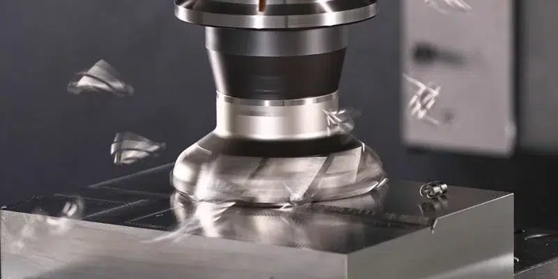
The milling run kicks off after all settings checked. The cutter ‘sweeps the face’, flattening the entire surface in passes. Vigilance is required—tool wear, vibration or a loose clamp can ruin the part.
Watch your inserts. Worn or chipped inserts scar or burnish the surface. A few quick insert swaps or speed tweaks and you can fix tool wear issues mid-job!
Stable cutting conditions = better results. Adjusting speeds or feeds half-run risks obvious lines or chatter. Crawl it, for a smooth even finish.
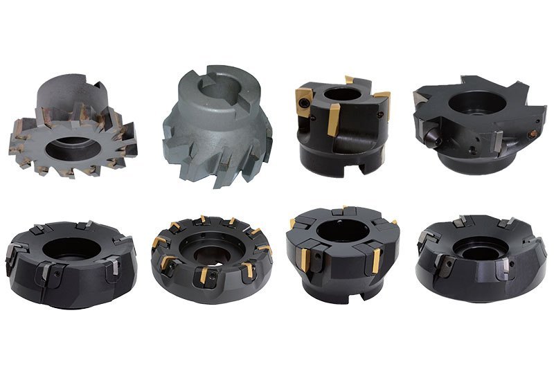
Essential Face Milling Tools
Face milling remains a staple operation in virtually every metal shop, particularly in general face milling applications. The proper tools — combined with good setup and technique — frequently dictate how long each job takes and how much it costs. Tool material, geometry, and design, along with proper application, all affect efficiency, durability, and performance in face machining tasks.
|
Tool Type |
Characteristics |
Common Applications |
|---|---|---|
|
Indexable Face Mills |
Replaceable inserts, rigid bodies |
Production, all metals |
|
Shell Mills |
Large diameter, used with arbors |
Large workpieces, roughing |
|
Fly Cutters |
Single-point cutter, simple design |
Fine finishes, prototypes |
|
Wiper Inserts |
Long edge, precise mounting needed |
High finish, final passes |
|
Round Insert Mills |
Variable chip load, entering angle |
High feed, interrupted cuts |
Choosing the right tool matters for both productivity and part quality. A 90-degree entering angle is ideal if you require a true 90-degree form. Having the right insert for the job—such as wiper inserts for finishing—can significantly reduce rework time and enhance the quality finish.
For effective face milling operations, try to maintain a minimum of 50% engagement. This ensures that every insert hits the cut at its prime, which ultimately increases tool life. If, for some reason, you have to cut across holes or slots, reduce the feed by 50 percent to keep chips thin and prevent tool damage.
Tool material is another critical consideration. Carbide inserts outlast high-speed steel and hold up better at higher speeds, but they come at an increased cost. Ceramics and cermets perform well on certain alloys and finish cuts but are brittle and require careful handling in specialized face milling applications.
Select the tool body and insert grade according to the hardness and abrasiveness of the workpiece material. Tool design doesn’t alter the speed and smoothness at which you can mill. A small entering angle allows you to drive feed rates higher, due to chip thinning, particularly when the axial depth of cut is low.
With round inserts, the depth of cut changes chip load and entering angle, so always remain comfortably beneath the maximum depth to maintain feed and evade problems in face milling procedures.
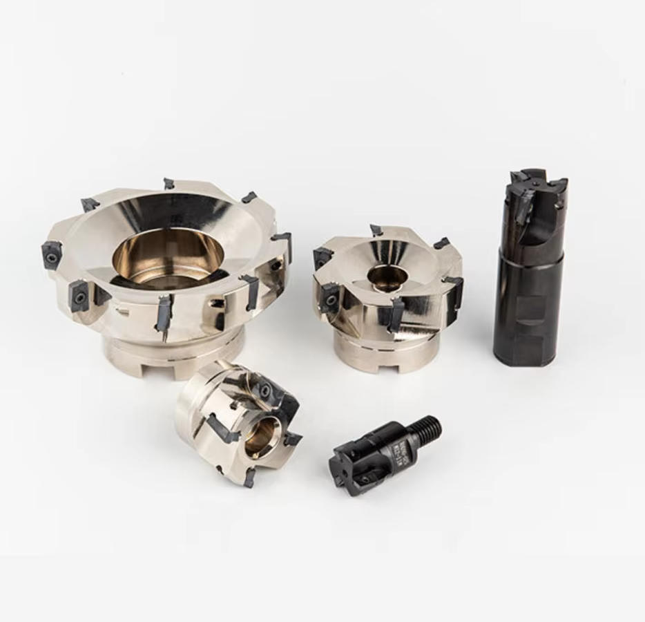
Indexable Face Mills
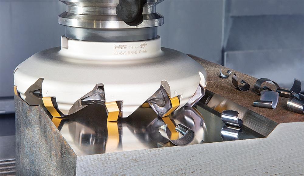
Indexable face mills employ replaceable inserts secured in a solid tool body. These tools are a roughing and finishing workhorse, tackling cast iron, steel, aluminum and beyond. Their key appeal is rapidity—exchanging inserts takes moments, so they’re ideal for manufacturing floors where every second matters.
Versatility is a bonus as well. You can fit the body with many types of inserts: square or round for rough jobs, wiper inserts for a glossy finish, or high-positive inserts for softer metals. Each insert geometry is selected for the specific job.
For instance, use a 90-degree insert when you require a true corner, and round ones are optimal for high feed rates and interrupted cuts. Tooling cost is lower over time, as well. Rather than chucking the entire cutter, you simply swap worn inserts.
Shell Mills
Shell mills are most effective with large pieces or when you need to remove a lot of metal quickly. They attach to an arbor, which enables you to utilize greater diameters and get wide faces in a single pass. It’s typical for heavy industry — think automotive frames or large machine housings.
Larger cutters result in greater material removal. The cutter diameter determines how much you can remove in each pass. You need to pair the cutter with the correct arbor to maintain low runout and prevent chatter.
Improper fit or setup reduces tool life and damages the finish.
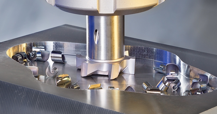
Fly Cutters
A fly cutter is a basic tool with a single-point cutting bit held in a rotating body. It’s simple to prepare and inexpensive to replace, which makes it a go-to for one-off work and smooth surfaces. Fly cutters excel when surface finish trumps speed, like with prototypes or short runs.
To achieve a quality cut, one must position the bit at the proper angle and adhere to shallow cuts. Feed the tool slowly and keep passes light. Fly cutters often attain a finer finish than multi-insert tools, but they’re slower and less suited for large-scale production runs.
Wiper Inserts
Wiper inserts are for high finish. They have a long edge and require careful mounting for optimal performance. These inserts are meant for the final pass, evening out any roughing tool marks.
Bad setup can mess up the surface, so verify alignment prior to each project.
Optimizing Face Milling Performance
Face milling operations are an everyday occurrence in contemporary manufacturing, specializing in producing flat surfaces with a quality finish at maximum rate. To optimize general face milling procedures, you need to control a number of variables, including speed, feed, depth of cut, tool engagement, and coolant strategy. Playing with these parameters impacts not just finish and precision but tool life and process stability.
Speed & Feed
Spindle speed and feed rate combine to sculpt the face milling operations result. Spindle speed, in RPM, determines how fast the face mill cutting tool spins. Feed rate is the speed that the work moves through the cutter, typically expressed in millimeters per minute. Just the right amount keeps you aggressive enough for efficient chip removal and minimal heat.
Excessive spindle speed, particularly on soft materials, can result in poor surface finish and rapid tool wear. Slow speeds cause built-up edge and rough cuts. Calculating optimal speed uses the formula: Cutting speed (m/min) = π × Diameter (mm) × RPM / 1,000. Material matters—aluminum usually employs speeds over 300 m/min, while steel might need 100–200 m/min. Cermet inserts, when used with high feed milling, yield shiny finishes, especially on steel.
Improper speed/feed values reduce tool longevity. Over-feed induces vibration, particularly in thin-walled parts. Selecting a cutter pitch that maintains more than one insert in cut eliminates chatter and minimizes vibration potential. Differential pitch face mills and radial compensation can keep chip loads in balance, further extending tool life.
Checklist for Adjusting Speed and Feed:
- Match speed to material and tool grade.
- Keep feed per tooth within tool maker’s guidelines.
- Use the same grade in wiper and working inserts.
- Opt for smaller insert radii on thin-walled pieces.
- Never under- or over-feed the chip load.
Depth of Cut
Depth of cut is the vertical distance the tool removes in a single pass. It directly affects the material removal rate and cycle time. A depth of cut of 2–6 mm is typical for mild steel, while harder metals demand smaller cuts. Selection of the proper depth is the secret to stabilization of forces and prevention of premature tool wear.
Drive that depth too far and you’re asking for rapid tool degradation and poor surface finish. Excessive depths—especially with large insert radii—can induce vibration and leave surface marks. Step-up modifications—increase the depth in small increments—provide enhanced control and safer cutting, particularly in tougher materials.
Tool Engagement
Tool engagement refers to how much of the cutter’s edge is engaged in the cut. Greater engagement generates greater cutting forces and heat, which can accelerate tool wear. Maintaining constant engagement, particularly when machining thin or flexible parts, minimizes the chance of chatter and bad surface finishes.
For best engagement, choose a cutter pitch that never has less than one tooth in the work. Shorter parallel lands and smaller insert radii are helpful when milling thin-walled parts, since these reduce vibration. There’s a direct link between engagement and finish: inconsistent engagement can leave visible marks or uneven surfaces.
By keeping the engagement constant during the cut, you have less vibration, consistent tool wear, and consistent surface quality. It’s highly beneficial for fast and fine jobs in particular.
Coolant Strategy
Coolant plays a crucial role in face milling operations by cooling the cutting zone and flushing chips away. Utilizing the appropriate coolant—water-based for general face milling applications and oil-based for hard alloys—can significantly enhance tool longevity and safety. For maximum benefit, coolant should be directed at the cutting edge of the face mill cutting tool.
How you apply coolant matters in milling procedures. Flood coolant is effective for normal machining tasks, while high-pressure nozzles are essential for tougher materials. Proper coolant application not only aids the cutter but also improves the fine surface finish by inhibiting built-up edges and minimizing burrs.
Effective coolant use translates into longer tool life, superior surface finishes, and safer working conditions in various milling projects. By ensuring optimal coolant management, machinists can achieve consistent surface finishes and enhance the overall performance parameters of their milling processes.
Distinguishing Milling Operations
Milling operations are essential in contemporary manufacturing, providing customized strategies for contouring, refining, and altering workpieces. Each kind of operation—face, peripheral, and slot—offers its own advantages. Understanding these distinctions optimizes machining efficiency, surface finish, and tool life.
The correct choice is dependent on part geometry, material, and desired finish.
|
Operation |
Surface Cut |
Typical Tool Used |
Key Application |
Distinct Feature |
|---|---|---|---|---|
|
Face Milling |
Flat face |
Face mill, shell mill |
Surface finishing, squaring |
Large tool, 45°/90° angle |
|
Peripheral Milling |
Outer edges |
Cylindrical cutter |
Contour shaping, deep cuts |
Teeth on periphery, axial cut |
|
Slot Milling |
Slots/grooves |
Slotting cutter, end mill |
Keyways, channels, grooves |
Narrow tool, precise path |
|
End Milling |
Faces & edges |
End mill |
Profile contours, pockets |
Versatile, various shapes |
|
Straddle Milling |
Both sides |
Two side cutters |
Parallel faces, simultaneous cuts |
Cuts two sides at once |
Versus Peripheral Milling
Peripheral milling describes cutting with the outside edge of the cutter parallel to the workpiece. The cutting occurs primarily along the tool’s edge, rather than its face, differentiating it from face milling.
Peripheral milling is ideal for contouring long edges, deep slots and intricate shapes. For instance, in mold making, structural parts and when the profile of a part is more important than surface flatness. This technique is preferred to face milling when precise edge definition and deep cuts are required.
This is the primary difference in cutter design – in peripheral milling, the cutter has teeth located on the circumference, while face milling cutters have cutting edges on the face and sometimes the periphery as well.
Peripheral cutters tend to be a smaller diameter and longer in length with deeper reach. Face milling is best for flatness and finish, whereas peripheral milling is better for more exact edge shapes and deeper profiles.
Versus End Milling
End milling employs a tool known as an end mill, which is capable of cutting in every direction. Unlike face milling, which only cuts with the face of the tool, end milling can cut both the surface and edges of a workpiece, making it suitable for pockets, slots, and profile contours.
End milling is great for projects which require complex shapes, such as electronic parts or mechanical groves. It’s the go-to for tiny parts, bespoke shapes, or if you need to drill down.
The distinction in tool geometry here revolves around the end mill’s flutes and cutting tips that enable side as well as end cutting. Face mills, which are large, have inserts or teeth configured for high-speed surface finishing.
Select end milling instead of face milling when versatility and complexity are needed.
Versus Slot Milling
Slot milling produces thin channels or grooves on a work piece. The cutter’s width corresponds to the slot and the operation moves the cutter along a defined path. Face milling smoothes flat surfaces, while slot milling operates within defined widths and depths.
Slot milling is essential to machining keyways, gear teeth or wiring channels. You’ll see it applied in automotive, electronics and machinery production.
Slot cutters are thin and robust, for secure, guided trajectories. Face mills are wider, designed for high speed, wide cuts. With slot milling, tool rigidity and accuracy are more important than velocity.
Choosing the appropriate milling operation guarantees that your final piece satisfies design, structural integrity and fit requirements.

Mastering Surface Finish
Surface finish, or the texture generated on a machined part, is an important element in face milling. It impacts how parts fit, move and appear. Where finish counts is in industries with a strong visual component and strict tolerances—for example, the automotive or medical device industries.
A carefully-managed surface finish extends a part’s durability, decreases friction and can even save money by preventing unnecessary polishing. Mastering this skill requires a close look at every variable: tool choice, machine stability, cutting parameters, and material.
The Role of Inserts
Cutting inserts lie at the heart of the milled surface finish. The insert’s shape, edge, and grade determine the level of finish — smooth or rough. For example, wiper geometry inserts can generate a flat, bright surface even at high feeds if carefully mounted, as their long edge is sensitive to misalignment.
Selecting specialized inserts for different materials, such as ceramics for hard alloys or carbide for steel, guarantees better wear resistance and finish. Always match the insert’s geometry to the job: more teeth (5–8 for finishing, based on cutter size) give a finer finish, while a strong-edged insert helps in tough, interrupted cuts.
For each job, reconsider your workpiece, feed rate, chip load and tool diameter prior to insert selection.
Mitigating Tool Wear
Face milling tool wear typically originates from heat, abrasive particles and high cutting speeds. When inserts wear, surface finish suffers and part quality declines.
- Choose the right tool material for the workpiece
- Set optimal feed rates and spindle speeds
- Use coolants to manage heat
- Rotate or index inserts before they fail
Proper machining parameters, like keeping the chip load low for finishing, slow down wear. For example, using a lower chip load and a shallow axial depth of 0.5–1.0 mm can help the tool last longer.
Regular checks let you catch wear early, keeping surface quality high and reducing downtime.
Advanced Finishing Techniques
Advanced finishing techniques—such as cutters equipped with wiper inserts, down-milling, or an off-center cutter—matter when you’re trying to achieve elite surface finishes. Specialized tools—including multitoothed types and custom edge profiles—allow you to boost feed rates two to three fold without sacrificing finish.
For best results, pair cutter diameter with workpiece (20–50% larger) and main cutting force to prevent chatter. In a crowd, a perfect surface finish distinguishes you, indicating craftsmanship and mastery of the process.
Practical Considerations
Check your workpiece and fixture stability. Select medium-duty face mills for aggressive work. Watch chip thinning when feed rates leap.
Manage axial depth of cut at each new setup.

Conclusion
Face milling is the most convenient and efficient method of cutting flat faces on metal and other hard materials. With the proper tool and intelligent settings, you achieve a nice finish and reduce your processing time. Setups count — so verify the cutter style, lock in your feeds and speeds, and examine chip flow. Catching the small stuff, such as tool wear or chip build-up, can make all the difference in the world. Face milling all over the world shops employ face milling to increase productivity and reduce expense. Need more slicing power? Keep your edge on tool trends and try out new tips in your own shop. Have a bench tip or story? Drop it in the comments and educate the rest of us.
Frequently Asked Questions
What is face milling?
Face milling operations involve removing material from the surface of a workpiece, resulting in flat, smooth surfaces ideal for various milling applications.
What tools are used in face milling?
Face milling employs a face mill cutting tool with multiple cutting edges, which is essential for various face milling operations.
How can I improve face milling performance?
Utilize sharp face milling cutting tools, appropriate cutting speeds, and proper feed rates; frequent tool care enhances efficiency and prolongs tool life.
What materials can be face milled?
Face milling operates on various materials, including metals like steel and aluminum, utilizing different types of face milling cutting tools.
How does face milling differ from other milling operations?
Face milling operations traverse the surface of a part to flatten it, while other milling techniques, such as end milling, are utilized for slot-cutting, grooving, or shaped cutting.
Why is surface finish important in face milling?
A nice finish from face milling operations makes parts slide together easily, reduces friction, and enhances the overall aesthetic.
What safety measures should be followed during face milling?
Always heed manufacturer safety precautions during face milling operations to avoid mishaps and ensure safety.