
Key Takeaways
- Boring machining is indispensable for creating exact, impeccably sized holes in countless materials, thus establishing itself as a vital process for superior manufacturing in multiple sectors.
- Knowing how to correlate tool geometry, speeds and feeds, and material properties can enable you to get the best boring results possible — and the surface finish and tolerances you want.
- Workpiece setup, tooling and machine parameters help to minimize vibration, tool deflection or heat effects and thereby improve machining efficiency.
- Quality inspection with precision measuring tools guarantees bored holes adhere to tight specifications, enabling consistent production standards and minimizing defect risks.
- Adopting emerging trends like process simulation, smart monitoring, and data analytics will continue to push the boundaries of boring precision, efficiency and versatility to novel materials.
- So take a look at your boring machining, embrace new technology and keep tweaking parameters according to material and operational feedback.
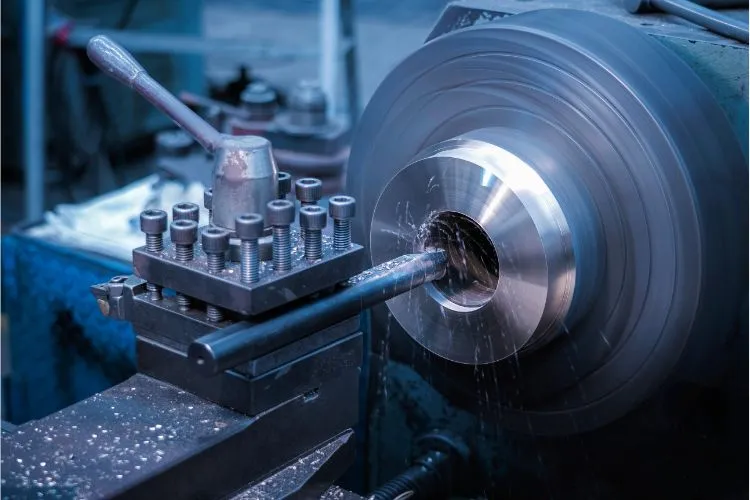
Boring machining is a technique that utilizes a single-point cutting tool to enlarge or finish the holes in metal, wood, or plastic. Shops employ boring to achieve tight tolerances and smooth surfaces in parts for engines, machines, and tools.
Standard configurations are the horizontal and vertical boring mills, both of which are found in workshops and factories. With boring, teams can tweak hole size, repair alignment or enhance roundness in a part post-drilling.
Boring tools are available in various shapes and sizes, therefore they can be suitable for small or larger work pieces. Machinists frequently opt for boring when a hole has to satisfy rigid fit or size requirements.
For more information on how boring works and how to select the appropriate borer, continue reading the following sections.
What is Boring Machining?
Boring machining is the accurate enlargement of an existing hole in a workpiece in order to achieve both an exact diameter and smooth finish. This method is required in lots of industries, as it yields holes with very fine tolerances and a surface quality that is demanded for things like engine cylinders or hydraulic components.
Boring can achieve surface roughness of 32–64 microinches Ra and tolerances of up to 0.01 mm (with right tooling and machinery). The method operates on any material and is employed globally in industries where precision and trust are paramount.
Common applications of boring machining include:
- Engine cylinder resizing for automotive and aerospace
- Hydraulic cylinder production
- Large industrial valve manufacturing
- Heavy equipment and machinery assembly
- Precision mold and die making
- Fabrication of turbines and compressors
Boring is an essential machining operation that you need to understand if you want to run effective machine shop operations. It requires diligent management of machine parameters, tooling, and operator expertise — each of which has an immediate impact on the quality and uniformity of the finished part.
1. The Core Concept
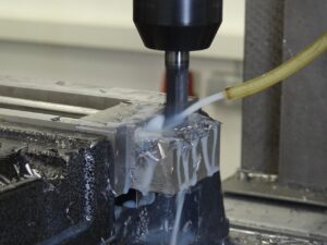
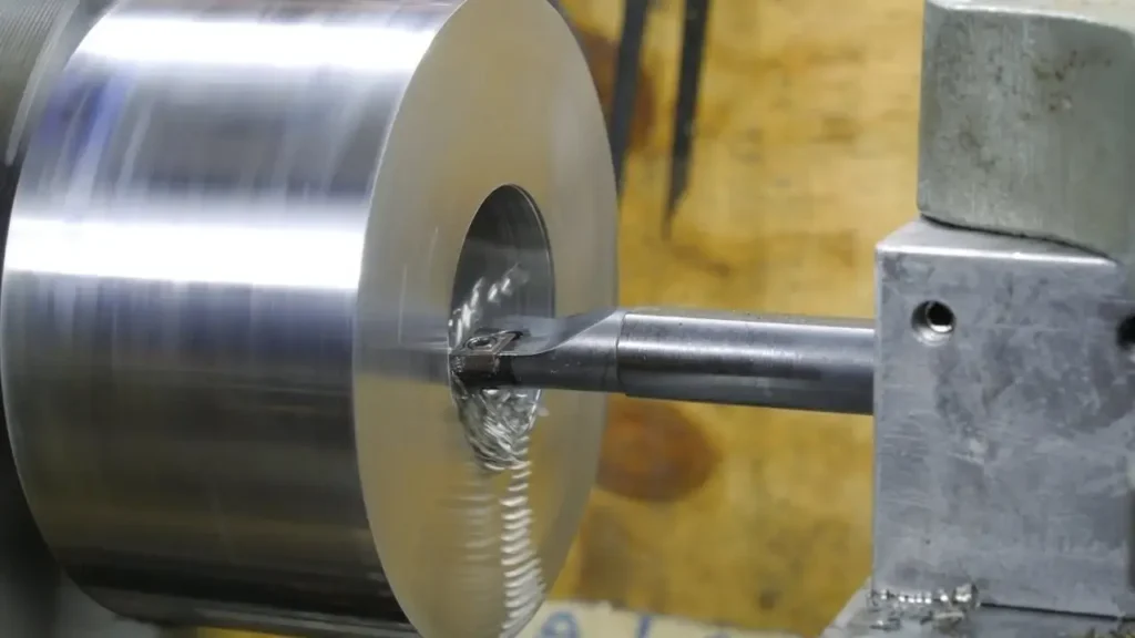
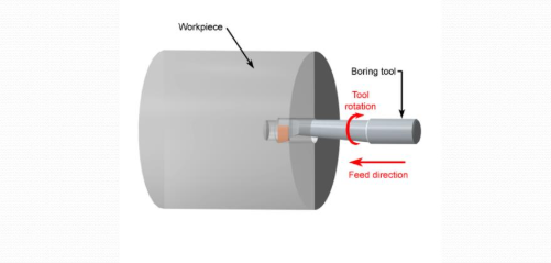
Boring is a machining technique whereby a rotary cutting tool is passed along the axis of an existing hole, shaving off layers of material to increase the size of the hole and improve the finish. Unlike drilling, which begins with a solid workpiece, boring processes always start with a hole that has already been created, whether through casting, drilling, or other machining methods. Boring machining technology ensures that the process is efficient and precise.
Boring tools are designed to suit various jobs, with tools scaled for different hole diameters and depths, from shallow holes to deep bores over a meter. Machine rigidity and the right cutting tool are crucial, as any flex or vibration can negatively impact boring quality and accuracy. Well-maintained machines and precise tool holders greatly assist in achieving consistent results.
Expert operators are indispensable in the boring machining processes. They install the tool into the machine, select appropriate speeds based on material hardness, and make adjustments until they achieve a perfect result, ensuring optimal boring performance.
2. The Primary Goal
The purpose of boring is to produce holes with precise diameter and smooth, consistent finish. This is particularly crucial in high-performance parts that must mate or seal, such as in engines or hydraulics.
Precise boring additionally supports increase output and reduces the possibility of scrapped materials through minimizing secondary-finishing treatments. When boring is done right, it makes the entire machining process more efficient.
Our tolerance capabilities allow performance and longevity of finished components. One of the few things precision boring sometimes determines is whether a part meets or misses rigorous quality checks, particularly in industries where reliability is paramount.
3. The Key Difference
Boring is not drilling. To drill is to make a hole from solid material, to bore is to make a hole bigger and more precise. Boring tools operate at slower speeds than drills to assist with control and minimize tool wear.
Boring is selected when a job requires a hole of a high level of precision or a diameter larger than what conventional drills can deliver. For instance, boring would be used to finish a cylinder in an engine block, whereas drilling could be used to only start the hole.
When to bore or drill always depends on the job at hand—size, finish, and accuracy.
4. The Common Misconceptions
A lot of people believe boring is only for the big holes, but we use it for tiny diameters as well—down to just a few millimeters—when precision is required.
Boring isn’t easy. It requires planning, exact tooling decisions and a stable setup. A few people think boring is strictly for metal, but it’s effective on plastics, composites and even wood in certain situations.
New boring machines and tools now enable more complicated shapes and more precision than ever before.
The Boring Machining Process
Boring machining is the process of enlarging and finishing holes many times after drilling or casting. Its primary objective is to attain tight tolerances and smooth surface finishes — indispensable in industries that swears by precision. This method includes a number of important stages, each demanding precise planning and implementation to guarantee the resulting bore is up to rigorous quality standards.
Main steps in the boring machining process:
-
Fix the workpiece in place using fixtures or vices, making sure it is stable during the operation.
-
Choose the right boring tool for the job, taking into account material, tool shape, and finish requirements.
-
Giddy-up the machine with the right speeds, feeds and settings, considering the material and bore depth.
-
Perform the boring, adjusting on-the-fly for smooth cutting.
-
Check the completed bore with fine measurement instruments ensuring it satisfies requirements.
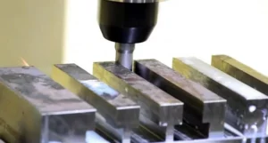
Workpiece Setup
Setup is a foundation of boring precision. First the workpiece has to be fixed on the machine table or in a chuck. Any movement while machining can result in misalignment, tool chatter or even dangerous situations. For most boring, even a slight shift will knock the bore out of tolerance — particularly when chasing tolerances as tight as ±0.0001 in (±0.0038 mm).
Alignment is just as important. If the workpiece axis is not coincident with the spindle axis, the bore will be out of round or off center. Use dial indicators or edge finders to verify your alignment. Before you begin, always verify the location with a test pass or by touching off the tool on the work. This helps keep faults in control and avoids wasting time fixing messes after the fact.
Tool Selection
Selecting the appropriate boring tool is more than just size. Among the key specs are tool material—M2 or M3 HSS for general work, P10 and P01 carbide for harder materials and higher speeds. Tool geometry, particularly the cutting edge angle and nose radius, affect chip formation, heat dissipation, and surface finish.
A single-point tool, however, is most common for boring because it provides the flexibility to change the tool shape to suit the bore diameter and finish. Match the tool with the work piece material. For instance, soft aluminum might require a different rake angle than hard steel. Tool length matters, too— large length-to-bore-diameters are eschewed to minimize deflection, which can spoil both tolerance and finish.
Good tooling allows for both vertical and horizontal cutting to more easily achieve the desired bore geometry.
Machine Execution
Successful implementation begins with proper machine parameters. Cutting speed, usually 60-150 m/min (200–500 fpm), depends on workpiece and tool material. Feed rates should strike a compromise between surface finish and tool life. For deep holes, slower feeds assist in controlling vibration and tool deflection.
Keep an eye on tool wear. Boring is sensitive to edge condition, and a dull tool can soon degrade accuracy and finish. Power needs may be 150 kW (200 hp) in industry, so stable machine dynamics are critical. Tweak speeds and feeds if you change material or bore depth. This adjustability facilitates various boring jobs and maintains output quality.
Quality Inspection
- Coordinate measuring machines (CMMs) for detailed 3D inspection
- Bore gauges for fast diameter checks
- Surface finish testers to assess roughness average (Ra)
- Plug gauges for go/no-go testing
Make sure to check the bore diameter and surface finish immediately following the boring machining processes. A smooth finish, typically between Ra 0.8–1.6µm (32–64µin), indicates good tool condition and stability. Utilizing specialized cutting tools minimizes the chances of overlooking tight specs. Test quality at every step, not just at the end, to catch machining errors early.
Boring Operations and Tools
Boring operations are some of the most interesting and useful machine operations, but some of the most complicated. Boring is only as efficient, high-quality, and accurate as the operation you select, the tools you use, and your knowledge of what affects the performance.
The table below presents a reference for common operation types and their applications:
|
Boring Operation Type |
Application Example |
Typical Tolerance (mm) |
Typical Surface Finish (Ra, µin) |
|---|---|---|---|
|
Rough Boring |
Initial enlargement of cast holes |
±0.25 |
125–250 |
|
Fine Boring |
Final finishing of precision bores |
±0.013 |
32–64 |
|
Line Boring |
Aligning multiple bearing housings |
±0.025 |
32–125 |
|
Blind Boring |
Closed-end engine blocks |
±0.013 |
32–64 |
|
Through Boring |
Hydraulic cylinder tubes |
±0.025 |
32–125 |
Operation Types
Rough boring cuts deep to remove the most material in the shortest amount of time in preparation for fine boring. Fine boring is important for parts that require tight tolerances and smooth finishes, like those used in aerospace or medical applications.
Line boring is employed when several holes need to be precisely aligned with each other, like engine block main bearing bores in cars or turbines. This operation maintains the axis of all holes straight, which is crucial for mechanical systems that require precise fits.
Blind boring makes holes of a designated depth without going through the material, and through boring opens the hole all the way. Blind boring is used for valve seats or closed-end cavities, though boring through is preferred for shafts or tubes.
Deciding between these boils down to the part’s purpose and design. Selecting the appropriate operation type is all about balancing your hole’s size, depth, finish and alignment requirements. Errors in this step can cause wasted work or expensive scrap, particularly in sectors where precision is paramount.
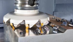
Essential Tooling
Boring bars and boring heads are the backbone of any boring operation. Boring bars vary in size and stiffness, so machinists can pair tool size to bore diameter and depth. Long bars deflect, which damages accuracy, particularly when boring deep holes.
Specialized tools, such as indexable boring heads, enable rapid tool changes and precise adjustments. Carbide-tips for the hard stuff, HSS for the softer metals. Coolant-through designs assist in heat removal, which maintains tool and workpiece integrity.
Choosing the appropriate tool for your material and job influences cutting speed, finish, and tool life. A mismatch can result in bad finishes and out-of-spec holes. Preprogrammed subroutines and CNC controls allow for repeatability of each pass, improving consistency and efficiency.
Proper tool care and replacement is necessary to prevent chatter, tool wear and bad surface finishes. A boring tool that’s more dull, instead, increases cutting forces, which decreases accuracy and strains the machine.
Tool Geometry
Tool geometry plays a crucial role in cutting performance and the overall machining quality of holes. Factors such as the edge, its angle and sharpness, as well as the rake and clearance angles, determine how the tool interacts with the material, affecting the cutting process and chip flow. Sharper cutting edges and favorable rake angles lead to clean cuts with less force, which minimizes tool wear, especially with hard materials that necessitate stronger tips to prevent edge disintegration.
The length of the boring bar sticking out from the tool holder, known as tool overhang, significantly impacts stability. Excessive overhang can induce deflection and vibration, resulting in poor finishes and out-of-tolerance holes. To achieve precise machining, minimizing overhang is essential, particularly for tight-tolerance jobs.
Tool geometry can be adapted for different materials. For instance, when boring aluminum, a larger positive rake is beneficial, while harder steels require a smaller angle and a more robust cutting tool. This adaptability is vital in various boring machining processes, ensuring optimal performance across different machining tasks.
In conclusion, understanding the interplay between tool geometry and material hardness is essential for achieving precision holes. Implementing best practices, such as minimizing tool overhang and selecting the right cutting tool, can significantly enhance the efficiency and quality of boring applications in machining operations.
Advanced Tooling and Machining Quality
Sophisticated boring tools, such as vertical boring machines and digital boring heads, significantly enhance precision machining by providing micron-level adjustments. These advanced boring machining processes enable higher cutting speeds, typically 60-150 m/min, depending on the material hardness.
Innovations in tooling have led to improved surface finishes, generally ranging from 0.8-3.2 µm Ra, while achieving ±0.013 mm tolerances in shallow holes. Enhanced chip control and machine rigidity protect against tool breakage, ultimately extending tool life.

Mastering Boring Parameters
Nailing boring parameters is critical to high precision and smooth finishes. Every parameter ties into tool life, surface quality and the requirement to adjust to hardness in material.
Summary of principal variables and their impact on boring:
|
Parameter |
Description |
|---|---|
|
Cutting Speed |
How fast the tool moves across the workpiece (m/min). |
|
Feed Rate |
Distance tool moves per revolution (mm/rev). |
|
Cut Depth |
Thickness of material removed per pass (mm). |
|
Boring Allowance |
Extra material left for finishing pass (mm). |
|
Tool Geometry |
Shape, angle, and size of boring tool tip. |
|
Coolant/Lubricant |
Fluid use for heat and friction control. |
|
Vibration Control |
Adjustments to reduce tool chatter, especially with long boring bars. |
Mastering these translates to more efficiency, less tool wear, and superior results. It requires tedious adjustments for each new content or task. Playing and monitoring shifts tunes the perfect parameters for every task.
Speeds and Feeds
Cutting speed and feed rate go hand in hand on every boring job. The former is how fast the tool cuts, and feed rate is how fast it moves per turn. Both impact the heat, tool life and finish.
To nail the numbers, you begin with the material—harder steels require slower, while aluminum can handle faster cuts. A simple baseline feed rate is 0.1-0.2 mm/rev. For instance, with hard stainless, you may need to reduce speed and feed to prevent the tool from burning out. Certain machinists rely on charts or software to determine optimal values, but practical adjustments are always required.
Cause if you’ve got speeds or feeds wrong, the tool wears out quick or the hole gets rough. Going too fast with a high feed can induce vibration, too, particularly on deep holes with skinny boring bars. Always first check the manufacturer’s charts for a safe range, then prepare test cuts to dial in for your setup!
Cut Depth
Cut depth determines how much material the tool removes with each pass. A shallow cut, say 0.3 mm, keeps the tool cool and the finish smooth, especially when you desire a fine surface or tight tolerance.
Make a deep cut, and you accelerate the work, but the blade dulls sooner. Too much at once, and you’re in danger of deflection or even tool breakage. For super-precise work or hard metals, it’s better to err on the side of caution and divide the work into multiple shallow passes.
For most work, don’t go under a 0.05 mm clearance or you’ll likely have difficulty achieving a clean finish, particularly with hard materials.
Material Influence
Content counts for boring. Soft metals such as aluminum cut easy but may smear if speeds are off. Hard alloys, such as titanium or hardened steel, require dedicated carbide-tipped physicals and reduced speeds.
Other metals resonate a lot, requiring slower feeds or more unusual cutter geometries. Being familiar with a few boring parameters–whether a job requires high precision or if the metal is difficult to machine–goes a long way to selecting the correct settings.
With practice, you figure out how to tweak for each instance, but always verify specs for each substrate before you begin.
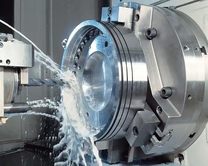
Coolant Strategy
Coolant keeps things running smooth by reducing heat and friction. Great coolant selections assist in preventing tool burnout and keeping chips from sticking.
Choose the appropriate coolant for the metal. For steel, water-soluble coolants do quite well. For aluminum, employ oil-based to prevent welding of chips.
Always direct coolant at the cut, not the tool. Flow enough to keep the tool cool, but not so much that it washes chips back into the hole.
Overcoming Common Challenges
Boring machining has always been exciting, complicated stuff because of the inherent variables that can influence accuracy, surface finish, and tool life. A lot of the issues come from tool setup, material, machine condition and process parameters. Tackling these problems early and precisely can go a long way toward keeping tolerances tight and finishes high quality.
Below is a checklist of common challenges, their causes, and solutions:
- Vibration and chatter: Use stable setups, balance tools, and select proper speed.
- Tool deflection: Choose rigid tooling and monitor loads.
- Thermal effects: Apply coolants and adjust speeds.
- Surface finish: Select correct tools and maintain optimal parameters.
Proactive steps—like machine calibration, fixturing, and general monitoring—can keep mistakes from becoming a repeating problem. Fine troubleshooting—loose fixings, feed rates, etc.—increases quality and reliability.
Vibration and Chatter
Vibration and chatter will result in bad hole geometry and rough surfaces. Chatter, specifically, causes noise and scoring inside the bored hole. If you hope to control chatter, you must understand its root causes—tool overhang, unstable machine, incorrect cutting speed.
Machine stability lies at the core of chatter reduction. Secure the workpiece with strong fixturing and reduce tool overhang. Employ short, stiff boring bars rather than long, flappy ones. For instance, a heavy-duty lathe with precise calibration and secure clamping goes a long way toward vibration-dampening.
Changing spindle speed or feed rate can disrupt those chatter-inducing harmonic frequencies. Opting for tools with the proper geometry and material—carbide, for instance, rather than HSS—minimizes vibration. For harder stuff or scalpel tolerance, leave at least a 0.05mm and finish allowance of 0.3-0.5mm.
Tool Deflection
Tool deflection fools hole precision and diameters, particularly in deep boring cuts. It commonly occurs when elongated serpentine instruments spring under stress. The longer the tool extends, the more it flexes.
Deep cuts, tough alloys, or high feed rates exacerbate deflection. A hard tool configuration assists a lot. Always attempt to minimize the tool. Use bigger-diameter boring bars or stiffer materials such as carbide. Keep an eye out for tool bending or chatter marks as it runs.
If you see sizzle, reduce the feed speed or take shallower cuts. Checking the completed hole with a bore gauge will indicate if deflection is an issue. Modify as required to maintain tolerances. Boring can be accurate to 0.0005 inches with due consideration.
Thermal Effects
Heat is a huge issue in boring as it wears tools quickly and distorts the hole size. Heat generated by friction between the tool and workpiece causes both the tool and the material to expand, potentially shifting the final bore dimensions.
Coolants have to be used to maintain temperature. Choose a coolant suitable to the workpiece material and apply sufficient flow for the cut size. Controlling speed and feed matters—going too fast accumulates more heat and destroys the tool edge.
For hard or heat-sensitive substrates, opt for blades in alloys or ceramics that dissipate heat more efficiently. Monitor the workpiece temperature while you’re at it to detect issues sooner.
Surface Finish
The way the tool moves across the surface determines the surface finish, which can be critical for part function and wear. Poor finish can come from bad tools, wrong parameters or not enough coolant.
Always choose keen, well-honed cutters and employ the proper geometry for the wood. The feed rate is crucial—a slower feed (0.1–0.2 mm/rev) tends to provide a finer finish.
Once bored, check surface roughness with profilometer or visually against a sample. If the finish is rough, attempt increasing the coolant flow, decreasing the feed or relocating to a sharper tool. For high-poly jobs, reserve a margin for a finishing run.

The Future of Boring
Boring machining processes are evolving rapidly, propelled by emerging trends in automation, intelligent controls, and the pursuit of speed and precision. More manufacturers are utilizing boring applications to create parts for cars, planes, and even new types of transport tunnels. As tools and systems become smarter, precision boring machining capabilities will continue to play an increasing role in how we construct and maneuver.
Process Simulation
Process simulation allows engineers to schedule boring jobs before they begin cutting. By simulating in software how a tool moves, how much heat it generates, or how a material reacts, teams can identify issues early and adjust their plans to save time and money. This is particularly important in boring machining processes, where precision is key.
Simulation tools can demonstrate what’s going to happen if you adjust speeds or feeds, or use different materials. This allows for more convenient access to fine surface roughness numbers, such as Ra 0.8–1.6 micrometers, which are now standard in high-precision work. Predicting these things reduces waste, which keeps costs down, particularly for massive tunneling endeavors that can amount to millions of dollars.
Running alternate ‘what if’ scenarios allows teams to observe the outcome of adjustments without endangering actual tools or workpieces. For instance, tool paths or coolant flow can be adjusted in the software to demonstrate how to prevent heat build-up or tool wear, especially in precision machining applications. Doing so aids decision-making and enhances the security and integrity of the end result.
To maximize the benefit of simulation, it’s wise to apply it early in the design process. By connecting simulation software to machine controls, adjustments can be trialed in virtual form before being deployed on the shop floor.
Smart Monitoring
Smart monitors with sensors that monitor boring machines in real time. These systems can detect vibration, tool wear, or even subtle changes in temperature, providing early warnings of trouble well in advance of a failure.
Real-time data from smart monitors can make boring quicker and more precise. If the system detects an issue, it can adjust speeds or feeds in real-time, assisting in maintaining surface finishes and precision within narrow tolerances.
Predictive maintenance utilizes this information to determine when a tool or machine requires attention. Rather than wait for something to break, teams can schedule service, which keeps machines humming and averts expensive downtime.
It takes planning to add smart tools to boring setups. It’s easier to begin with machines that are already digitally controlled, then incrementally add sensors and software.
Advanced Materials
Boring tools today employ hard alloys and ceramics that wear longer and resist heat. Workpieces from new composites or metals need these high-end tools to get smooth, tight finishes, particularly in planes or cars where every part must fit just right.
These can be hard to cut, requiring adjustments in speed, tool geometry, and coolant. For instance, when boring fresh aerospace alloys, heat builds quickly, and the tool must be stiff and well-cooled to maintain the hole’s circularity.
Data Analytics
Data analytics allow teams to monitor every nuance of a boring task. By monitoring tool wear, speeds, feed rates — and even coolant consumption — teams can identify patterns and adjust processes for optimized performance.
Over time, these insights make it easier to select just the right tools and settings for every job, resulting in more consistent finishes and less waste.
Checking performance data post-job helps your team learn and improve. This continuous cycle of feedback and adaptation is essential for staying ahead of new technology and more challenging work.

Conclusion
Boring is one of the jewels of metal work. Shops employ it to hit precise size and finish targets. The proper boring tool and solid rig maintain the cut spot on and accurate. Shops must monitor speed, feed and depth cautiously. Even minor tweaks can change the way a part comes out. Shops have chatter, tool wear and heat, but clever solutions keep things moving. Digital technology now assists with live verification and quicker setups. Learning, testing and adapting shops have strong, smooth parts every time. To fuel your work, follow fresh tips and tech in boring. Tweet your successes and concepts with the community. Let’s make each other better, one bore at a time.
Frequently Asked Questions
What is boring machining?
Boring machining processes are a method that opens up and refines the precision of pre-drilled holes using a single-point cutting tool, making it essential in metalworking and various manufacturing techniques.
What are the main types of boring operations?
The primary varieties of boring machining processes include line boring, back boring, and horizontal boring, chosen based on workpiece size, hole location, and precision machining requirements.
Which tools are commonly used for boring?
Typical examples of boring machining tools include boring bars, boring heads, and specialized cutters, with tool choice depending on material hardness, hole diameter, and desired finish.
How does boring differ from drilling?
Drilling produces new holes, while boring machining processes smooth and enlarge them, offering superior surface finish and precision machining capabilities.
What parameters are important in boring machining?
Key parameters such as cutting speed, feed rate, and depth of cut are crucial in machining processes, as they ensure precision machining and prolong tool life.
What are common challenges in boring machining?
Common problems such as tool deflection, vibration, and rough surface finish can be mitigated through the use of optimal boring techniques and rigid setups.
How is boring machining evolving with technology?
Modern boring processes utilize CNC machines and high-tech sensors, enhancing precision machining capabilities and ensuring higher productivity and reliable results.